Before learning about strain gauges, learn what “strain” is first.
External force applied to an elastic material generates stress, which subsequently generates deformation of the material. At this time, the length L of the material extends to L+ΔL if applied force is a tensile force. The ratio of ΔL to L, that is ΔL/L, is called strain. (Precisely, this is called normal strain or longitudinal strain.) On the other hand, if compressive force is applied, the length L is reduced to L- ΔL. Strain at this time is (- ΔL)/L. Strain is usually represented as ε . Supposing the cross sectional area of the material to be A and the applied force to be P, stress σ will be P/A, since a stress is a force working on a definite cross sectional area. In a simple uniaxial stress field as illustrated below, strain ε is proportional to stress σ, thus an equation σ = E x ε is satisfied, provided that the stress σ does not exceed the elastic limit of the material. “E” in the equation is the elastic modulus (Young’s modulus) of the material.
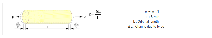
Because a strain is a ratio between length of two parts, it is a quantity having no dimension. Usually it is represented in a unit of 1 x 10⁻⁶, since the ratio of deformation is often very small. For example, supposing L to be 100mm and ΔL to be 0.1mm, strain ε is indicated as 1000 x 10-6 strain, because “0.1mm/100mm=0.001=1 x 10-3=1000 x 10-6”. To indicate comparatively large strain, “% strain” is also used. In this case, 1% strain equals to 10000 x 10-6 strain.
So strain is a very small value.
What is STRAIN GAUGE
Strain changes in only very minute values, so how is this measured with a strain gauge?
External force applied to a metallic material generates physical deformation and electrical resistance change of the material. In case that such material is sticked onto test specimen via electrical insulation, the material produces a change of electrical resistance corresponding to the deformation. Strain gauges consist of electrical resistance material and measure strains proportional to the resistance changes.
STRAIN GAUGE CONFIGURATION
In order to measure change in the resistance value due to extension of metal (resistor), how is a strain gauge structured?
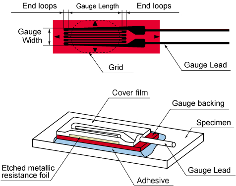
A strain gauge is constructed by forming a grid made of fine electric resistance wire or photographically etched metallic resistance foil on an electrical insulation base (backing), and attaching gauge leads.
STRAIN GAUGE PRINCIPLES
We have seen how a strain gauge is structured. Next the principle of how strain is measured based on change in a resistance value due to extension of metal (resistor) will be explained.
When strain is generated in a test specimen and a strain gauge is atstached, the strain is relayed via the gauge base(electrical insulation) to the resistance wire or foil in the gauge. As a result, the fine wire or foil experiences a variation in electrical resistance. This variation is exactly proportional to the strain.

Normally, this resistance change is very small and requires a Wheatstone bridge circuit to convert the small resistance change to a more easily measured voltage change.

The voltage output of the circuit is given as follows.

Here, if R=R1=R2=R3=R4 the resistance of the strain gauge changes to R+ΔR due to strain. Thus, the output voltage Δe (variation) due to the strain is given as follows.

When measuring with a strain gauge, it is connected to an instrument called a strainmeter. The strainmeter configures a Wheatstone bridge circuit and supplies exciting voltage. Measured strain is indicated on a digital display and/or output as analog signals.
Technical Terms
Gauge Length
This dimension represents the actual grid length in the sensitive direction.
Gauge Resistance
The gauge resistance is the electrical resistance of an unbonded gauge at room temperature and subject to no external stress.
Gauge Factor
The amount shown in the following equation is called the gauge factor. In this equation, ε indicates the strain generated due to uniaxial stress in the direction of the strain gauge axis. ΔR/R shows the ratio of resistance change due to strain ε.

Transverse Sensitivity
The gauge also exhibits sensitivity in the direction perpendicular to the axial direction. The amount shown in the following equation due to the uniaxial strain (εt) in the direction perpendicular to the gauge axis, and the resistance variation generated thereby, is called transverse sensitivity (Kt).
Temperature Compensation Range
The temperature range within which thermal output meets a specification with a self temperature compensated gauge.
Self Temperature Compensated Gauge
A strain gauge made so that thermal output is as little as possible when adhered to a material to be measured with a particular coefficient of thermal expansion within a specified temperature range. We term self temperature compensated gauges of within ±1.8 × 10⁻⁶ strain per 1℃ capability a self temperature compensated gauge.
Operating Temperature Range
This range is the temperature range within which a strain gauge can be used continuously under appropriate conditions.
Strain Limit
The strain limit is the maximum amount of strain under which a strain gauge can operate under a given condition without suffering damage.
Fatigue Limit
The number of times a certain amount of strain is applied mechanically to an adhered strain gauge until change of 100×10−6 strain with regard to an initially indicated strain is observed.
Strain gauge shapes
Strain gauges are available in shapes suitable for any application.
Select a gauge shape that meets measuring goals.
| Number of elements | 1 element | 2 element | 2 element |
|---|---|---|---|
| Shape |  |  | |
| Name | Single-element | Cross | Cross |
| Arrangement | – | Stacked | Plane |
| Number of elements | 3 elements | 3 elements | 5 elements |
| Shape |  |  |  |
| Name | Rosette | Rosette | 5-element |
| Arrangement | Stacked | Plane | – |
Selecting a gauge length
Measurement object
As required by the object being measured, a short-length gauge may be used for localized strain measurement, and a long-length strain gauge for averaged strain measurement.
Averaged: For nonhomogenous materials, an adequate length of material that allows strain to be averaged is required. To measure nonhomogenous material such as concrete consisting of cement and aggregate, a gauge with a length about 3 times that of the aggregate grain size is used.
| Gauge length | Measurement object |
|---|---|
| 0.2 to 1mm | Stress concentration measurement |
| 2 to 6mm | General strain measurement in metal |
| 10 to 20mm | General measurement of mortar, wood, FRP, etc. |
| 30 to 120mm | General measurement of concrete |
Response
The response of a strain gauge depends on the gauge length and the elastic wave (longitudinal wave) of the material being measured.
| Gauge length (mm) | 0.2 | 1 | 3 | 5 | 10 | 30 | 60 |
|---|---|---|---|---|---|---|---|
| Steel | 660 | 530 | 360 | 270 | 170 | – | – |
| Concrete | – | – | – | – | 120 | 50 | 20 |
Gauge width
A narrower-type gauge (FLK type) with the same gauge length is also available. Select a strain gauge with a narrow gauge width for narrow specimens such as pipes and round sticks.

Name of each part of strain gauge
Pictures of each strain gauge given for the strain gauge series are shown enlarged so they are easier to see. Note that they are not shown actual size.
New system that does not generate measurement error
For strain gauge measurement, various bridge configurations are employed according to the number of strain gauges to be used and measuring purpose. In quarter bridge configuration, three wire method is widely used to remove the effect of temperature to gauge leadwire resistance. However, some measuring error occurs owing to gauge factor correction due to leadwire resistance and variation in the contact resistance of connection part. Our developed 1-gauge 4-wire strain measurement method serves not to induce any measurement error ascribable to the gauge factor correction and contact resistance.
(Japanese Patent No.3546203)
New system that does not generate measurement error
Our originally developed 1-gauge 4-wire strain measurement method has the following advantages over the conventional quarter bridge 3-wire method.
Leadwire Resistance
In conventional method, as thick and short leadwires as possible are recommended to keep the resistance of leadwires lower. On the contrary, as the 1-gauge 4-wire method is not influenced at all by the leadwire resistance, it is possible to connect a thin and long leadwires to strain gauges.
Contact resistance
In conventional method, leadwire extension and connection to a measuring instrument are done by soldering or the use of exclusive connector. As the 1-gauge 4-wire method is not affected at all by contact resistance, a modular plug can be used. Because the modular plug makes lead wire extension and connection to the instrument possible by merely plugging in, the efficiency of wiring work and prevention of wiring mistake are achieved and also lead free connection is possible.
Comparison: quarter bridge 3-wire method and 1-gauge 4-wire strain measurement method
A comparison of the conventional quarter bridge 3-wire method and 1-gauge 4-wire strain measurement method highlights these features.
No effect from change in lead wire resistance value
| Quarter bridge 3-wire method | 1-gauge 4-wire strain measurement method | |
|---|---|---|
| Lead wire thickness | Thick | Thin |
| Lead wire weight | Heavy | Light |
| Lead wire material | Use of same item required | Use of same item not required |
| Lead wire sheath color | Same color depending on measurement | Use of same item not required |
| Load on specimen | Heavy | Light |
| Transport cost | Large | Small |
No effect from change in contact resistance value where connectede
| Quarter bridge 3-wire method | 1-gauge 4-wire strain measurement method | |
|---|---|---|
| Quick-connector connection | Not possible | Possible |
| Soldering | Required | Not required |
| Wiring workhours | Long | Short |
| Miswiring | Yes | No |
| Environmental friendliness | Soldering contains lead | Lead-free |
More Information
Measurement systems
With our data loggers TDS-630/-530/-150, using a TDS-602/-303 connected directly to the modular jack of the built-in switching box allows 1-gauge 4-wire strain measurement simply by using a compatible switching box.
TDS-150 100 ch (built-in max. 50 ch), battery operation
TC-32K Handheld, 5 ch (external switching box), strain, temperature, voltage, 4 “AA”
ISW-50G 1-gauge 4-wire compatible, switching box with built-in ADC
IHW-50G 1-gauge 4-wire compatible, built-in ADC, high-speed switching box
SSW-50D Compatible with 1-gauge 4-wire strain measurement, semiconductor relay type (50 ch)
FSW-10 1-gauge 4-wire compatible, channel unit for TDS-150.
A typical bridge configuration to cancel axial load in bending measurement is shown in “Half bridge with 2-active gauges eliminating tensile strain” in the web page. Here, the strain gauge R1 is mounted on the front side the strain gauge R2 is mounted on the back side. These two strain gauges are connected in half bridge. In this configuration, when full bridge is used, each two strain gauges are mounted on the front side and the back side. If we suppose the front gauges R1 and R2 and the back gauges R3 and R4, these strain gauges are connected in a Wheatstone bridge clockwise R1, R3, R2, R4 (not R1, R2, R3, R4). A typical bridge configuration to cancel bending in axial load measurement is shown in the upper figure of “Full bridge” in the web page. (The lower figure of Full bridge is for torque measurement.) Here, the strain gauge R1 and R3 are in axial direction and the strain gauge R2and R4 are in circumferential direction.
If you have any questions, please be kind to let us know. We would recommend to use two two-element strain gauges like FCM-2.8-350.
Note: When a full bridge is configured on a plate or cylinder, we think it better to bond each one two-element strain gauges on oposite sides of the specimen. Visit Transducer Gauges
Yes, we have a fully trained team of engineers and can provide you training on all the equipment we sell apart from them we
keep running some small courses so please look our Events and News sections updates.