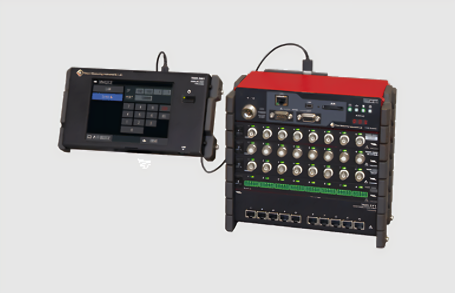
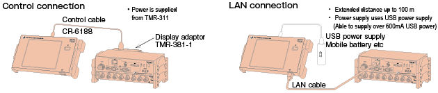
By the connection of display unit TMR-381, stand-alone control of multi-recorder becomes possible such as setting of various units, measurement control (balancing / measurement start and stop / automatic measurement setting), monitoring (T-Y sweep / Y-T cont. / X-Y / numerical) and setting file management. When dedicated I/F cable is used for connection, external power source is not required because this unit is operated by the power supply from the control unit TMR-311. It is also possible to use a LAN cable for connection. In this case, extension is possible up to 100 meters and a USB mobile battery can be used as the power source.
Since the display unit operates independently of the control unit, measurement will be continued even if the display unit is turned off after the automatic measurement is started. The display unit may be connected only for confirmation of data and/or stop of measurement.
Specifications
| Type | TMR-381 |
|---|---|
| Indicator | Color TFT LCD, 320 x 240 dot (with touch panel) |
| Function | Various settings Measurement start/stop, Balancing control Value monitoring, Waveform monitoring |
| External dimensions | 200 (W) x 30 (H) x 110 (D) mm |
| Weight | Approx. 750 g |
| Power supply | 600 mA MAX |
| Standard accessory | Display adaptor TMR-381-1 Dedicated I/F cable CR-6188 |
 Back
Back
Frequency processing library TMR-311-01 (optional)
This is an optional frequency processing library for the TMR-300 series of multi-recorders. It realizes a histogram recording system that digitally processes measurement data according to a preset program and records them as frequency counts. Six frequency analysis methods are available: maximum and minimum value method (PEAK/VALLEY), maximum and minimum value method (MAX/MIN), amplitude method (AMP), time method (TIME), level crossing method (LEVEL), and rain flow method (RAIN).
- Up to 80 analyses can be performed in low-speed mode with a sampling interval of 1 ms or morez
- Multiple analysis methods can be set up for the same channel
Specifications
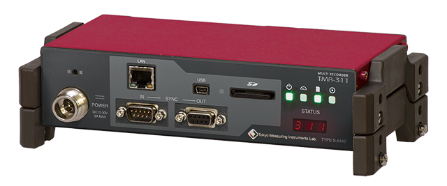
| Type | TMR-311 | |
|---|---|---|
| Number of measuring points | 80 at maximum (with up to 10 networked units, by selection of input unit) |
|
| Sampling | 0.01 to 0.09ms (set by every 0.01ms) 0.1 to 0.9ms (set by every 0.1ms) 1 to 1000ms (set by every 1ms) 512, 1024, 2048, 4096, 8192 Hz |
|
| Trigger function | Data trigger | Data of optional channel (optional input level, or relative level from start) |
| Command trigger | Command from interface | |
| Timer trigger | Real time, Interval | |
| Synchronization of multiple units | Synchronization of sampling and trigger for up to 4 units of TMR-311 (320 measurement points) Maximum extension between two units: 100m |
|
| Recording media | SD card 4GB to 32GB (SDHC high speed mode class 10) | |
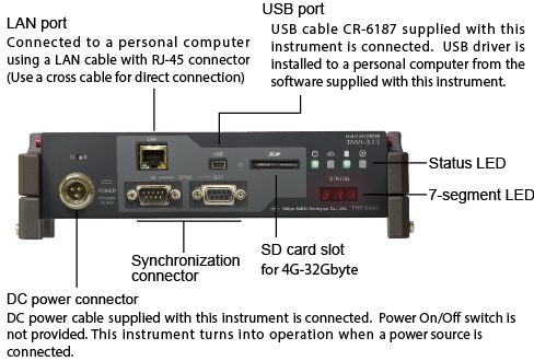
| Interface | LAN, USB, Wireless LAN (AP mode, IP fixed) * *: Built-in wireless LAN is not available for overseas model. |
|
| Indication | Status LED (status, IP address, etc.) | |
| External dimensions | 200(W) x 50(H) x 100(D) mm (excluding projected parts) | |
| Weight | Approx. 900g (including rubber protectors) | |
| Power supply | DC 10 to 30V, 0.6A at maximum (when 12V supplied, single unit) AC 100 to 240V, 50/60 Hz, 100VA at maximum (when using optional AC adapter CR-1897) |
|
This unit is for measurement of strain in full bridge connection. Measurement of DC voltage is also possible by using optional attenuator cable (CR-4010).
Specifications
| Type | TMR-321 |
|---|---|
| Number of measuring points | 8 channels |
| Input | Strain, Voltage (when using optional cable CR-4010) |
| Applicable gauge resistance | 120 to 1000 Ω |
| Bridge excitation | DC 0.5 V, 2 V |
| Measuring range | ±20000 x 10-6 strain (bridge excitation 2 V) ±80000 x 10-6 strain (bridge excitation 0.5 V) |
| External dimensions | 200(W) x 25(H) x 100(D) mm (excluding projected parts) |
| Weight | Approx. 550 g (including rubber protectors) |
| Power supply | DC 10 V to 30 V 0.2 A at maximum (12 V) (supplied from TMR-311) |
This unit is for measurement of strain. Using the supplied detachable bridge box (SB-120T or SB-350T; selected when ordering) or terminal block, measurement in quarter bridge 3-wire, half bridge and full bridge connection is possible.
Specifications
| Type | TMR-322 |
|---|---|
| Number of measuring points | 8 channels |
| Input | Strain |
| Applicable gauge resistance | 120 to 1000 Ω |
| Bridge excitation | DC 0.5 V, 2 V |
| Measuring range | ±20000 x 10-6 strain (bridge excitation 2 V) ±80000 x 10-6 strain (bridge excitation 0.5 V) |
| External dimensions | 200(W) x 25(H) x 100(D) mm (excluding projected parts) |
| Weight | Approx. 550 g (including rubber protectors) |
| Power supply | DC 10 V to 30 V 0.2 A at maximum (12 V) (supplied from TMR-311) |
This unit is for measurement of strain in full bridge connection with carrier wave bridge excitation, which is resistant to noise. It is the most suitable for the measurement on site where induction noise or commercial power noise is expected.
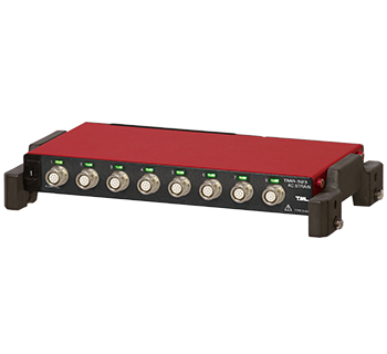
Specifications
| Type | TMR-323 |
|---|---|
| Number of measuring points | 8 channels |
| Input | Strain |
| Applicable gauge resistance | 120 to 350 Ω |
| Bridge excitation | 0.5 Vrms, 2 Vrms, 5 kHz |
| Measuring range | ±20000×10-6 strain (bridge excitation 2 Vrms), ±80000×10-6 strain (bridge excitation 0.5 Vrms) |
| External dimensions | 200(W) x 25(H) x 100(D) mm (excluding projected parts) |
| Weight | Approx. 660 g (including rubber protectors) |
| Power supply | DC 10 V to 30 V 0.3 A at maximum (12 V) (supplied from TMR-311) |
This unit is for measurement of DC voltage within the range of ±52 V.
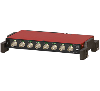
Specifications
| Type | TMR-331 |
|---|---|
| Number of measuring points | 8 channels |
| Input | Single end (unbalanced) Isolated between channels |
| Settable range | ±52 V, ±20 V, ±10 V, ±5 V, ±1 V |
| External dimensions | 200(W) x 25(H) x 100(D) mm (excluding projected parts) |
| Weight | Approx. 550 g (including rubber protectors) |
| Power supply | DC 10 V to 30 V 0.25 A at maximum (12 V) (supplied from TMR-311) |
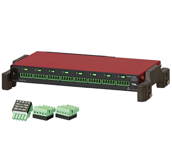
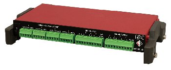
This unit is for measurement of temperature with thermocouple T, K or J, and also for measurement of DC voltage within ±20 V. Since the terminal blocks for connection are detachable from the unit main body, connection works can be made easily.
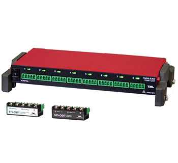
Specifications
| Type | TMR-332 |
|---|---|
| Number of measuring points | 8 channels |
| Input | Thermocouple (T, K, J), Voltage, Isolated between channels |
| Measuring range | T: -200 to +400 ℃ K: -200 to +300 ℃ J: -200 to +200 ℃ DC voltage: ±20 V |
| External dimensions | 200(W) x 25(H) x 100(D) mm |
| Weight | Approx. 550 g |
| Power supply | DC 10 V to 30 V 0.25 A MAX (12 V) (supplied from TMR-311) |
Conversion and output of data in analog voltage for strain, temperature, etc. measured by other units
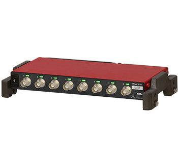
Specifications
| Type | TMR-341 |
|---|---|
| Number of measuring points | 8 channels |
| Output signal | Voltage output of measured data obtained by other measurement unit (measurement point for output can be set optionally) Output of the result of accumulation or subtraction of up to 4 points |
| Output level | ±10V, ±5V, 0 ~ +5V (5kΩ load) |
| External dimensions | 200(W) × 25(H) × 100(D)mm |
| Weight | Approx. 550 g (including rubber protectors) |
| Power supply | DC 10 ~ 30V, 0.3A at maximum (12V)(supplied from TMR-311) |
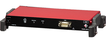
Built-in CAN interface enables data recording and output from CAN bus
Simultaneous measurement of vehicle integrated control signals, acceleration, torque, and stress, enabling control system analysis.
Specifications
| Type | TMR-351 |
|---|---|
| Protocol supported | CAN Specification V2.0B active standard ISO11898(High Speed) |
| Communication speed | 10k to1Mbps |
| Number of messages | Max. 64 (Receiving: Max. 64, Sending: Max. 62) |
| Number of Signals | Max. 512 |
| Data Receiving | Records messages with specified ID Number of recordable IDs: 0 to 64 Data length: 1 to 8Byte When monitoring and recording with the TMR-311, the signal (2byte)×8CH |
| Data Sending | Data output on specified channel Number of outputtable data: 0 to 64 Data length: 16bit (2Byte) |
| Record | Max. 32 Mbyte (internal RAM) All messages are recorded separately after data from other measurement units are recorded by TMR-311. |
| Function | Data bit specification, endian setting Selectable between data frames, remote frames, and return on receipt of remote frames for transmitted messages Selectable message transmission cycle Selectable listen-only mode |
| Indication | Unit number setting switch CAN SIGNAL: CAN bus signal RECEIVE:Receiving SEND: Transmitting |
| Connector | D-Sub 9-pin connector (male) CAN input withstand voltage -27V to 40VDCMAX |
| Dimensions | 200(W)×25(H)×100(D)mm (excluding protruding parts) |
| Weight | Approx. 530g (including rubber protector) |
| Power supply | 0.2A MAX(12V)(supplied by TMR-311) |
Count and frequency conversion functionality for digital pulse signal from rotary encoder and/or speed sensor Various kind of digital input/output signal is available necessary for measurement Trigger signal (start measuring) input, sampling clock input/output and alarm signal (upper and lower limit setting) output
Specifications
| Type | TMR-353 |
|---|---|
| Frequency measurement and pulse count | |
| Number of measuring points | 4 channels |
| Input signal waveform | Square or sin wave |
| Measuring voltage range | Minimum input signal : 50mVp-p Maximum input signal : 12V |
| Frequency response | 1Hz~100kHz |
| Power output | Output voltage : 5V/12V Output current : 5V/20mA, 12V/25mA (5V and 12V cannot be used simultaneously) |
| Counter range | 0~29,999 count 0~899,999,999 count (1+2CH 32bit counter mode) |
| Function | Frequency measurement, number of count measurement, rotary encoder calculation, A-phase, B-phase, Z-phase and angle calculation |
| Digital input | |
| Number of input | 4 channels |
| Input pulse width | 0.5ms or more (response frequency : 1kHz and less), negative logic |
| Function | Triger input, external sampling input, marker signal input Balance signal input, calibration output signal input (0/+/-) Start measurement(RUN), stop measurement(HALT), Pause measurement(PAUSE) (settable arbitrary for each input) |
| Digital output | |
| Number of output channels | Trigger output : 1 point sampling signal output : 1 point Alarm (upper limit) : 1 point Alarm (lower limit) : 1 point |
| Output form | Open corrector output |
| External dimensions | 200(W) × 25(H) × 100(D) mm |
| Weight | Approx. 550 g |
| Power supply | 0.5A MAX(12V) (Supplied from TMR-311) |
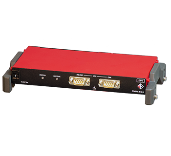
This unit is a component of the “Automobile Related Measurement System” and records driving position information from the Global Positioning System (GPS).
Specifications
| Type | TMR-354 |
|---|---|
| Compatible GPS receiver | General-purpose RS-232C type Communication speed 11520bps NMEA protocol (without power supply) |
| CAN type Communication speed 250 kbps (with power supply) | |
| Position measurement accuracy | GPS/Galileo/GLONASS/BeiDou Positioning accuracy 2.5mCEP Update cycle 1Hz *Depends on the GPS receiver used |
| GPS Data | Longitude in 0.0000001° increments Latitude in 0.0000001° increments Elevation in 1-meter increments Time in 0.1 second Speed in 0.1 km/h Distance in meters Azimuth in 0.1° increments *Depends on the GPS receiver used |
| GPS Time Setting | TMR-311 Timing with GPS Time Data *Use local time |
| Data transmission | Record received GPS data When monitoring and recording with TMR-311, select GPS data (2 bytes) x 8 CH |
| Record | Max. 32 Mbyte (internal RAM) All GPS data is recorded separately after recording data from other measurement units with TMR-311. |
| Function | Monitor, setting of channels to record Setting of recording format Regional time settings TMR-311 time setting |
| Display | Unit number setting switch STATUS: GPS receiver signal RECIVE: Receiving |
| Connector | D-Sub 9-pin connector (male) RS-232C compliant x 1 CAN compliant x 1 |
| External dimensions | 200(W)×25(H)×100(D)mm |
| Weight | 530g |
| Power supply | 0.2A MAX(12V)(supplied by TMR-311) |
Specification
| Type | TMR-361 |
|---|---|
| Number of measuring points | 4 channels |
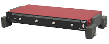
| Compatible sensors | Charge output type accelerometers, Charge sensitivity 0.1~10pC(m/s2) |
| Input connector | Miniature connector 10-32UNF |
| Allowable charge Input | 10000pC |
| Measuring range | 250pC range resolution 0.01pC Equivalent to 250m/s2 at charge sensitivity 1pC/(m/s2) 2500pC range resolution 0.1pC Equivalent to 2500m/s2 at charge sensitivity 1pC/(m/s2) 10000pC range resolution 0.4pC Equivalent to 10000m/s2 at charge sensitivity 1pC/(m/s2) |
| Frequency response | 1Hz~10kHz |
| Low pass filter | |
| Cutoff frequency | Digital filter 1Hz~1kHz (settable in unit of 1Hz) Pass (Analog filter 10kHz) -3dB ± 1dB |
| High pass filter | |
| Cutoff frequency | Digital filter Fixed 1Hz |
| External dimensions | 200(W) × 25(H) × 100(D) mm |
| Weight | Approx. 550g |
| Power supply | 0.35A MAX(12V) (Supplied from TMR-311) |
Specifications
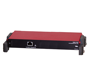
| Type | TMR-372 |
|---|---|
| Synchronizable units | TMR-211 |
| Multi-unit synchronization | Max. 4 units (including master) If there are multiple TMR-311 units, be sure to connect them to the master unit. The number of TMR-311 units connected to a TMR-372 is limited to 9. |
| Delay time | At the fastest sampling rate of 100 kHz (10 μs) When measurement is started from TMR-311, the data from TMR-311 is delayed by 390μs relative to the data from TMR-211. When measurement is started from TMR-211, the data from TMR-311 is delayed by 350μs relative to the data from TMR-211. |
| External dimensions | 200(W)×25(H)×100(D)mm |
| Weight | Approx. 500g |
| Power supply | DC10V to 30V 0.25A MAX (12V) (supplied from TMR-311) |
Specifications
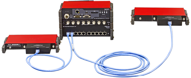
| Type | TMR-371 |
|---|---|
| Number of connection of distribution unit | 1 (for one TMR-311) |
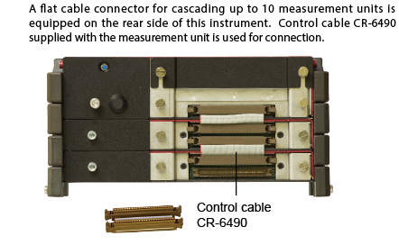
| Number of connection of measurement unit | 10 (including measurement units directly connected to TMR-311) |
| External dimensions | 200(W) x 50(H) x 100(D) mm (excluding projected parts) |
| Weight | Approx. 800 g (including rubber protectors) |
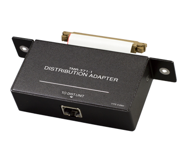
Specification
| Type | TMR-371-1 |
|---|---|
| Number of connection of distribution adapter | 10 (for one TMR-371) |
| Number of connection of measurement unit | 1 |
| Extension distance | 100 m |
| External dimensions | 130(W) x 25(H) x 50(D) mm (excluding projected parts) |
| Weight | Approx. 150 g |