Strain Measurement
We provide strain gauge measurement Services for over 40 years. With TML’s best technology and equipments on our side we always have an advantage over others. Our usual goal is to understand our valued clients requirement and suggest an optimized solution.
Strain Gauge Coding System
| F | General purpose |
| WF | Waterproof construction |
| PF | Concrete use, Polyester foil gauge |
| P | Concrete use, Polyester wire gauge |
| FLM/WFLM | Concrete use, Metal backing strain gauge |
| MF/QMF | Magnetic field use |
| PMF | Concrete use, Embedment type strain gauge |
| YE/YF/YHF | Post-yield strain (Large strain) measurement |
| PMFLS | Asphalt use, Embedment type strain gauge |
| LF | Low elastic material use: Wood, Gypsum |
| PFLW/PLW | Low elastic material use: Wood |
| GF | Low elastic material use: Plastics |
| BF/UBF | Composite material use |
| DSF | High endurance use, Fatigue test |
| CF | Cryogenic temperature use |
| CEF | Wide range temperature use |
| QF/ZF/EF | High temperature use |
| SFA | Stress measurement |
| AW | Weldable strain gauge |
| BTM | Bolt axial strain measurement |
| DD | One-side gauge |
| FAC | Crack detection gauge |
| TF | Strain gauge type temperature measurement |
| KM | Concrete/Asphalt embedment use, strain transducer |
| FGMH | Frictional Strain Checker |
| FGAH | Frictional Axial strain transducer |
| FGDH | Frictional Torque Sensor System |
| L/LA/LK/LX/LG/BX/BY | Single-axis |
| LAB/LKB/LGB GOBLET | |
| C/CA/LC/CS/CB | |
| CAB GOBLET | 2-axis Rosette (0°/90°) |
| R/LR/RA/RAS/RS | 3-axis Rosette |
| RAB GOBLET | (0°/45°/90°) |
| XV/YV/BXV/BYV | 5-element Single |
| CV | 5-element Rosette (0°/90°) |
| CT | Torque |
| LT | 45° Single-axis |
(*1) Not always coded 0°/90° 2-axis 0°/45°/90° 3-axis
Gauge Length in mm
| Functions (*2) | Applicable gauge | |
|---|---|---|
| T | Integrated with thermocouple | Applicable to most of strain gauges |
| A | Left 45° | QFLT |
| B | Right 45° | QFLT |
| W | Large Width | FLAB, QFLAB, Some of 350Ω strain gauges. |
Gauge resistance in Ω (standard 120Ω not presented)
| 3 Composite material | 17 Stainless steel/Copper alloy | ||
| Ceramic (Si3N4) | 2.6 to 3.3 | SUS304 | 16.2 |
| CFRP | 3 to 5 | SUS310 | 15.8 |
| 5 Composite material | SUS316 | 16.0 | |
| Ceramic (SiC) | 4.6 | SUS321 | 16.7 |
| CFRP | 3 to 5 | Copper | 16.7 |
| 8 Composite material/glass | Beryllium copper | 16.6 | |
| Soda glass | 7.9 | Brass | 16.7 |
| Titanium | 8.9 | 23 Aluminium | |
| Titanium alloy (Ti-6Al-4V) | 8.8 | Aluminium | 23.4 |
| 11 Mild steel | Aluminium 2024-T4 | 23.0 | |
| Mild steel (0.1-0.2C) | 11.8 | Lead and its alloy | 29.0 |
| Hard steel (0.4-0.5C) | 11.2 | Gypsum | 25.0 |
| Cast iron | 10.5 | Polyimide | 20 to 30 |
| Hastelloy-276 | 11.2 | 28 Magnesium | |
| Inconel 600 | 13.3 | Magnesium alloy | 27.0 |
| Inconel 750 | 12.1 | 50 Plastics | |
| Monel | 13.5 | Epoxy (Cast) | 45 to 65 |
| SUS 630 (17-4PH) | 10.8 | 70 Plastics | |
| SUS 631 (17-7PH) | 10.6 | Acrylics | 70 |
| Concrete | 7 to 13 | ABS | 74 |
| Polyacetal (POM) | 80 | Polyacetal (POM) | 80 |
| Polycarbonate (PC) | 66-70 | ||
| Polystyrene (PS) | 60-80 | ||
Strain gauges using leaded solder as standard specifications are optionally available with lead-free solder used. The option code “-F” is appended to the type number of lead-free solder used gauges to discriminate them from conventional strain gauges using leaded solder. The option code “-F” is omitted for strain gauges with CE marking such as GOBLET series.
| with 2-wire | Standard length 1 , 3 , 5 m |
| Lwith 3-wire | Standard length 3 , 5 m |
| Suffix Code | Description |
|---|---|
| LJB / LJB-F | 0.08mm2 paralleled vinyl leadwire |
| LJBT / LJBT-F | 0.08mm2 3-wire paralleled vinyl leadwire |
| LJC / LJC-F | 0.11mm2 paralleled vinyl leadwire |
| LJCT / LJCT-F | 0.11mm2 3-wire paralleled vinyl leadwire |
| LJD | 0.3mm2 paralleled vinyl leadwire |
| LJDT | 0.3mm2 3-wire paralleled vinyl leadwire |
| LH / LH-F | 0.02mm2 twisted vinyl leadwire |
| LHT / LHT-F | 0.02mm2 3-wire twisted vinyl leadwire |
| LS / LS-F | 3.2mm-dia. shielded vinyl leadwire |
| LTSA / LTSA-F | 3mm-dia. shielded 3-wire vinyl leadwire |
| LTSB / LTSB-F | 5mm-dia. shielded 3-wire vinyl leadwire |
| LQM / LQM-F | 0.08mm2 polypropylene 4-wire paralleled leadwire with modular plug |
| LXT / LXT-F | 3-wire paralleled special vinyl leadwire |
| LJRA / LJRA-F | 2-wire twisted cross-linked vinyl leadwire |
| LJRTA / LJRTA-F | 3-wire twisted cross-linked vinyl leadwire |
| LJQTA / LJQTA-F | 3-wire twisted cross-linked polyethylene leadwire |
| TLJBT / TLJBT-F | Temperature-integrated 3-wire paralleled vinyl leadwire |
| 6FBTLT / 6FBTLT-F | 3-wire twisted fluorinated resin (FEP) single-core leadwire |
| LP / LP-F | 0.14mm/0.18mm polyurethane leadwire |
| LU / LU-F | 0.14mm/0.18mm polyester leadwire |
| LE / LE-F | 0.14mm/0.18mm polyimide leadwire |
| 6FASDLT / 6FASDLT-F | 3-wire twisted fluorinated resin (FEP) leadwire (Surface treatment (tetra-etching) is not required) |
| 6FBSDLT / 6FBSDLT-F | 3-wire twisted fluorinated resin (FEP) single-core leadwire |
| 6FCDSLT | 5mm-dia. shielded fluorinated resin (FEP) leadwire with shield |
| 4FADLT / 4FADLT-F | 4-wire twisted fluorinated resin (PTFE) leadwire |
| 4FBDLT / 4FBDLT-F | 3-wire twisted fluorinated resin (PTFE) single-core leadwire |
Option –F
The leadwire pre-attachment is available using lead-free solder. For the leadwire pre-attached strain gauges using lead-free solder, the option code “-F” is appended to the type number to discriminate them from conventional leadwire pre-attached strain gauges using leaded solder.
Color coding for test specimen
Most of strain gauges are self-temperature-compensated. Strain gauges in Series F, UF, CF and WF are color coded in three types according to the material for compensation.
| Test specimen | Coefficient of thermal expansion | Backing color | Gauge type exampled |
|---|---|---|---|
| Mild steel | 11×10-6/℃ |  Red |
FLA-5-11 |
| Stainless steel Copper alloy | 17×10-6/℃ |
Brown
|
FLA-5-17 |
| Aluminum | 23×10-6/℃ |  Green |
FLA-5-23 |
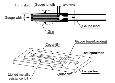
Name of each part of strain gauge

What is STRAIN
External force applied to an elastic material generates stress, which subsequently generates deformation of the material. At this time, the length L of the material extends to L+ΔL if applied force is a tensile force. The ratio of ΔL to L, that is ΔL/L, is called strain. (Precisely, this is called normal strain or longitudinal strain.) On the other hand, if compressive force is applied, the length L is reduced to L- ΔL. Strain at this time is (- ΔL)/L. Strain is usually represented as ε . Supposing the cross sectional area of the material to be A and the applied force to be P, stress σ will be P/A, since a stress is a force working on a definite cross sectional area. In a simple uniaxial stress field as illustrated below, strain ε is proportional to stress σ, thus an equation σ = E × ε is satisfied, provided that the stress σ does not exceed the elastic limit of the material. “E” in the equation is the elastic modulus (Young’s modulus) of the material.
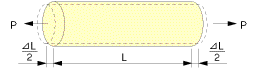

ε = ΔL/L
ε : Strain
L : Original length
ΔL : Change due to force P
Because a strain is a ratio between length of two parts, it is a quantity having no dimension. Usually it is represented in a unit of 1×10⁻⁶, since the ratio of deformation is often very small. For example, supposing L to be 100mm and ΔL to be 0.1mm, strain ε is indicated as 1000×10-6strain, because “0.1mm/100mm=0.001=1×10-3=1000×10-6“. To indicate comparatively large strain, “% strain” is also used. In this case, 1% strain equals to 10000×10-6strain.
STRAIN GAUGE CONFIGURATION
A strain gauge is constructed by bonding a fine electric resistance wire or photographically etched metallic resistance foil to an electrical insulation base using an appropriate bonding materials,and attaching gauge leads.
SELECTING STRAIN GAUGES
Strain gauges are provided with many convenient features, but they also have limitations. Each strain gauge has its limitations in terms of temperature, fatigue, the amount of strain, and the measurement environment. These limitations must be examined before a strain gauge is used.
- Strain Gauge Features
- Simple construction with a small mass and volume so as not to interfere with the stresses on the specimen.
- Short distance between measuring points for localized evaluation.
- Good frequency response for tracking rapid fluctuations in stress.
- Simultaneous measurement of multiple points and remote measurement.
- Electrical output for easy data processing.
Detailed material
Contributions
Record Tech Electronics welcomes Case History contributions. If you have a project you would like to be considered for inclusion in our Case History section, please submit details along with 2 or 3 suitable images to the Record Tech Electronics Web Manager.